This case describes three separate interventions for positional lower extremity SSEP changes over the course of the first half of a L2-4 PTP with varying degrees of improvement in SSEP data. Interestingly, the evoked potential of most concern (left saphenous) remained the most stable compared to other waveforms throughout the procedure.
Most of these changes occur either before retractors are placed, or on the contralateral side of interbody placement (working from left side). We show that it is possible to develop SSEP changes via overtightening of pelvic hip pads + strap.
Patient was a 77 year old male with a history of low back and left-sided leg pain into his knee. He is 180cm tall and weighs 103kg. He denied any focal weakness. He has a history of previous left knee arthritis and replacement, coronary artery disease, and bladder cancer. He has lumbar stenosis, spondylosis with radiculopathy, and lumbar spondylolisthesis at the L2-4 levels.
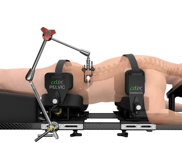
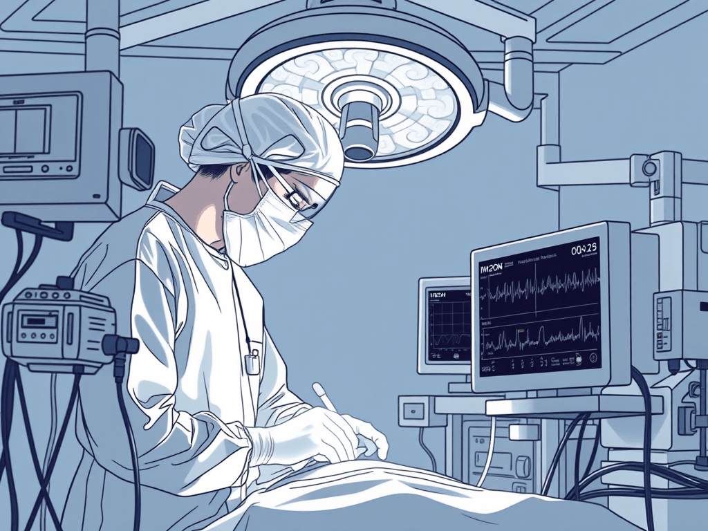
Patient was positioned in the standard position for the prone transpsoas (PTP) approach (ATEC). Patient was turned on a Jackson table with chest and hip pads placed in the traditional fashion. Hip pads were secured with strap across buttocks.
PTP Patient Positioner – ATEC Spine
Neuromonitoring included Somatosensory Evoked Potentials (SSEP) of the Posterior Tibial (standard ankle stimulation) and Saphenous (proximal- needle electrodes placed in thigh) Nerves and lower extremity electromyography (EMG), utilizing needle electrodes for vastus medialis & lateralis, biceps femoris, and anterior tibialis muscles (Standard ATEC SafeOp PTP Test). TOF was placed at the standard left peroneal nerve and was 4/4 throughout nerve & screw stimulation. All nerve stimulation trials were >10mA and all screws stimulated at >20mA.
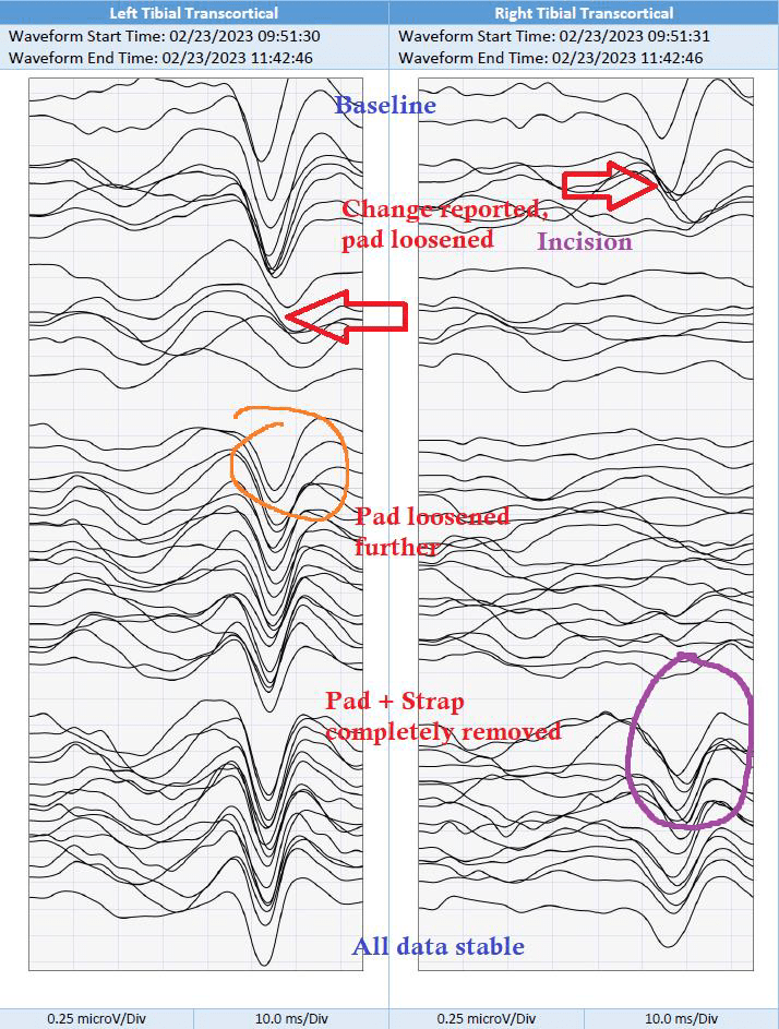
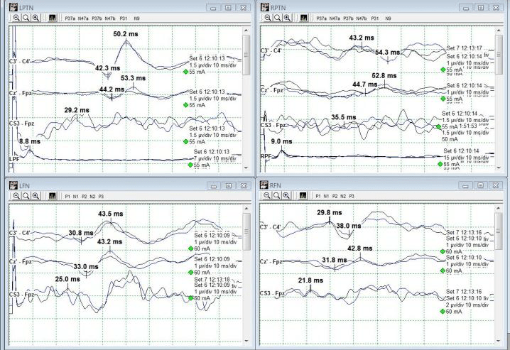
Shortly after initial traces and baselines – and just around incision – a change in right tibial (Cortical + Transcortical) SSEPs were noted and reported (red arrows). Technical factors such as stimulation failure were ruled out as well as anesthetic factors, which had started at 1.5% and then 2.5% Sevofluorane during positioning, were mitigated by utilizing a total intravenous anesthetic (TIVA). MAP was maintained in the high 70s/low 80s. Propofol and remifentanil were maintained at 100mcg/kg/min and 0.10mcg/kg/min respectively throughout the remainder of the procedure. Left tibial SEPs and bilateral saphenous transcortical responses began to decrease in amplitude and demonstrate morphological changes while these changes were being discussed and troubleshooted.
The hip pad was not readily viewable due to c-arm telescope blocking, so it was unclear what could have been affecting positioning. Once c-arm was moved, the apparent right pelvic pad was loosened slightly to maintain current desirable positioning. A slight improvement in Right Saphenous and Left Tibial SEP was noted (orange circle) but further deterioration of bilateral Tibial SEPs persisted.
Right tibial SEPs (Cortical + Transcortical) at this point were nearly abolished. The right pelvic pad was loosened further with moderate recovery of the bilateral saphenous SEPs (green circle).
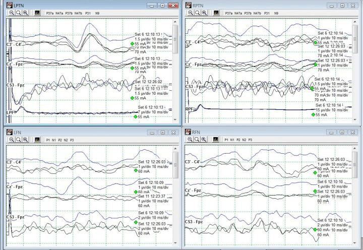
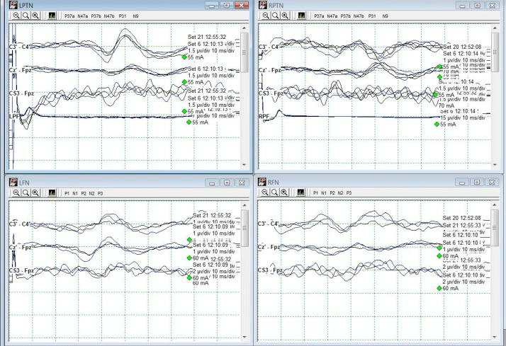
Finally, the strap was cut and the pelvic pad was completely removed which allowed for a very rapid return of tibial cortical and transcortical responses (purple circle). These responses remained stable throughout the remainder of the procedure with no additional alerts. The patient went home the following day with no apparent deficit.
Caution and care should be taken when placing and securing pelvic hip pads and straps. Improper positioning and overtightening of pads can lead to nerve fiber ischemia and peripheral nerve injury.
Neuromonitoring must begin early and performed continuously throughout all surgical stages to identify changes in IONM data.
Left & Right Saphenous Cortical SSEPs. Right Saphenous improvement circled in orange. Left saphenous demonstrates mild improvement after initial intervention.Left & Right Saphenous Transcortical responses. Improvements circled in green following second attempt at loosening pelvic padding.Left & Right Tibial Cortical responses. Changes from baseline noted with red arrow. Improvement circled in purple. Left improved with further loosening, right only returned after complete pelvic pad removal.Left & Right Tibial Transcortical responses. Changes from baseline noted with red arrow. Improvements circled in orange and purple. Left improved with further loosening, right only returned after complete pelvic pad removal.
All data remained stable up and including to the end of monitoring.
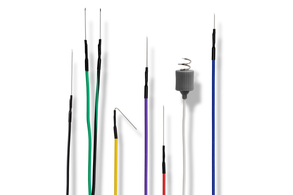
Subdermal needle electrodes carry inherent risk of needlestick exposure to not only the IONM technologist but other personnel:
Needle-stick injuries can expose staff to serious bloodborne pathogens including Hepatitis C, Hepatitis B, and Human Immunodeficiency Virus (HIV).
Preventing needle-stick injuries is the best way to protect yourself and others from these infections!
According to the CDC, there are around 385,000 reported needlesticks among hospital-based healthcare personnel (2015). More occur in other settings, with potentially half being unreported.
Luckily the potential viral load from an IONM needle is low due to there being no hollow bore of the needle, but it is still considered a high risk.
When and how often do needlestick injuries occur during IONM? Who gets stuck?
According to a retrospective study of IONM-related needle-sticks by Tamkus & Rice (2013): There were 174 injuries reported across 50,665 monitored surgeries (0.34% of their group).
Most needle-sticks for IONM technologists during removal of the needles (52%), and during patient positioning for non-IONM personnel (67%).
For example, surgeons are particularly at risk with abdominal leads during patient positioning when their arms are pulled back which may remove tape and expose the needle.
Nurses and anesthesia personnel are at risk during positioning of head, arms, and wrists.
Fast turnovers and positioning can add pressure on the IONM technologist to place quickly with improper handling technique.
Best, acceptable, and unacceptable practices for placement and removal of subdermal needles:
Always prep needle sites with an alcohol wipe to prevent infection.
Communication: Inform personnel of where needles are placed when they may be hidden due to patient positioning – Back of neck (‘Crv’), behind arms (Triceps), behind legs (Pop Fossa, Gastroc, Femoris). Do not use jargon that may not be quickly understood (“PTN needle is out!”)
Troublesome electrodes such as those on the wrists (Ulnar, Brachioradialis, Thenars), abdomen, and legs (Psoas) should also be pointed out. Consider using extra tape or Tegaderm.
Slow down placement: Slowing down a beat during placement and properly securing electrodes will save more time than dealing with a needle-stick injury.
Remove needles slowly: Ripping all electrodes out from under the drapes at once can cause more problems than they solve. Needles can bend and cause tissue damage & bruising. The wire can break and leave a loose needle under the drapes. It is recommended to hold the electrode wire near the needle, peel away the tape, remove the needle and inspect it.
Hold pressure on sites to prevent bleeding. Clean any excess blood and always remove tape and adhesive. Using scissors, cut the extra length of wire from the needle to prevent over-filling the sharps container.
An acceptable practice is securing electrode wires with tape if no stress loops are placed. Always ask staff before taping wires to the bed.
Removing electrodes by yanking wires from the foot of the bed is unacceptable and potentially harmful to the patient, staff, and yourself!
Finally, if a needlestick injury does occur, follow your company’s and hospital’s protocols!
Tamkus A, Rice K. Risk of Needle-Stick Injuries Associated With the Use of Subdermal Needle Electrodes During Intraoperative Neurophysiologic Monitoring. J Neurosurg Anesthesiol. 2013;26; 65-68
The femoral nerve is the largest branch of the lumbar plexus. It originates from posterior L2 divisions to L4, and innervates the surfaces of the medial and anterior thigh. The saphenous nerve is monitored as the largest cutaneous branch of the femoral nerve to reflect femoral nerve sensory function during indicated procedures. For the lateral lumbar and eXtreme lateral interbody fusion (LLIF and XLIF) procedures, which are mostly performed between the L2-L5 levels, this main branch is mostly at risk by way of retraction systems in situ. This case presents an example of saphenous nerve SSEP changes with relatively stable tibial nerve SSEPs, further reinforcing the importance of saphenous nerve monitoring during lateral procedures.
NuVasive XLIF Procedure Animation – NuVasive
This patient was a 45-year old female, presenting with complaints of excruciating lower back and left-sided leg pain with associated numbness through her hip and into her foot. She was also beginning to experience these symptoms on the right. She had no weakness. She states she had no history of diabetes, hypertension, seizure, or stroke. Her prior surgical history included a lumbar fusion at L4-5 and a cervical fusion.
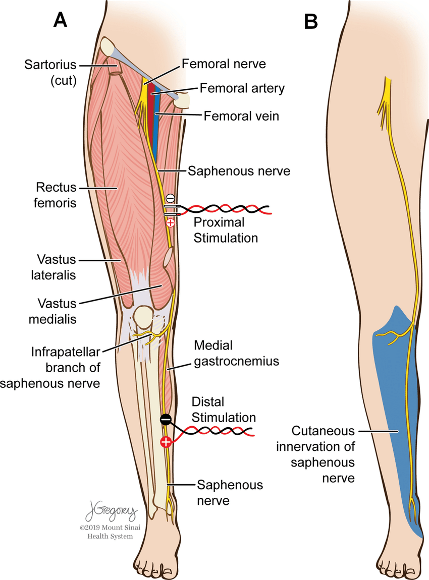
She was positioned in the lateral decubitus position with her left side up and knees bent towards her chest. Tape was wrapped around the hips, just above the knee, and across the lower legs to keep her in place on the bed. Pillows were placed between the knees. Anesthetic protocol included a total intravenous method, utilizing between 100- 150mcg/kg/min of propofol and a steady 0.30mcg/kg/min of remifentanil. Surgeon requested SSEP monitoring (Saphenous + Posterior Tibial + Ulnar) with NuVasive EMG for dilator / nerve stimulation. Needle electrodes were placed in the standard placements for PTN, SN (Fig 1), & UN stimulation with additional needles behind the popliteal fossa and sticky pads over the femoral nerve as back-up for saphenous nerve.
Figure 1: Stimulation placement for saphenous nerve SSEPs (figure from Silverstein et al. 2015)
Baseline SSEPs were monitorable from all extremities except for RPTN, which was just barely marginally present. (Fig 2). Initial RPTN SSEPs were monitorable but quickly appeared to wash out following additional traces. PTN SSEPs were stimulated at 60mA 0.5ms 2.09Hz, SN SSEPs at 70mA 0.5ms 2.09Hz, and UN SSEPs at 30mA 0.3ms 2.09Hz. PTN + SN SSEPs were interleaved on the same timeline to more quickly acquire lower extremity data.
Figure 2: Baseline PTN & SN SSEPs
A change in the LSN SSEPs was reported almost immediately after setting baselines and prior to any implant sizing or placement (Fig 3). Some decompression work had begun but it was believed based on stimulation trials that the surgeon was well away from any significant nerve roots or groups. No problems in SSEP stimulation delivery were apparent based on movement during stimulation in all 4 extremities.
The recommendation therefore was made to maintain an elevated blood pressure (declined due to surgeon preference for lower mean blood pressure for less bleeding) and to remove any distraction down at the legs. The surgeon declined this at the time as well, stating that he had a good deal of retraction in place and that it would interfere with surgical maneuvers. For the time being, the legs were only gently moved around and shaken to attempt to restore some blood flow to the legs.
Figure 3: Loss of Left SN SSEP (Bottom Left)
Immediately after instrumentation was in place, the tape across the hip, knee, and foot was cut away and removed. The left leg was lifted off the right and set back into its original position, only without tape. Within one data set, LSN SSEPs were within baseline parameters (from 90%+ reduced) and Right PTN SSEPs were much more reliable in cortical channels (Fig 4). Some improvement was seen in LSN subcortical responses as well.
Figure 4: Recovery of Left SN SSEP after tape removal. Mild improvement also seen in R PTN SSEP (slightly more repeatable).
The patient was then flipped to prone for posterior instrumentation with no significant events. She woke up with no additional deficits, and not much psoas pain which is very common following lateral spine surgeries. Because the actual data changes occurred in only LSN SSEPs, this case demonstrates the usefulness of saphenous and/or femoral nerve SSEPs in not only directly assessing L2-L4 nerve root function, but also as a reflection of possible malpositioning during lateral spine surgery.
Monitoring PTN + SN/FN SSEPs on the same timeline can be helpful to evaluate most at-risk sensory pathways simultaneously. Positioning effects can occur prior to any monitoring and must therefore be approached quickly in the absence of monitorable baselines in patients with no pre-operative deficits.
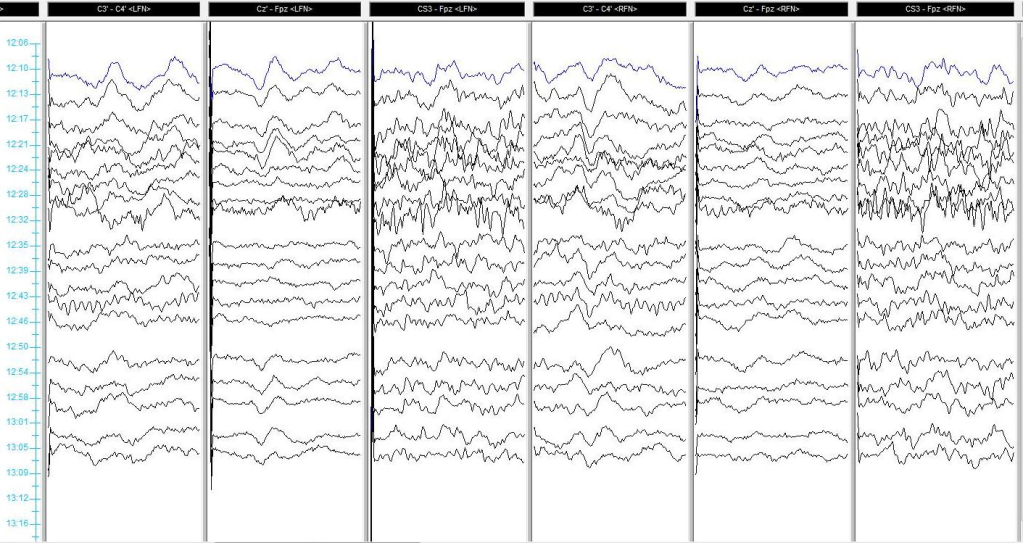
Figure 5: History stack of SN SSEPs illustrating loss + recovery. Change reported @ 12:24, Tape Removed @ 12:54.
For more reading, please see the always-fantastic Dr. Silverstein’s article:
Silverstein J, Mermelstein L, DeWal H, Basra S. Saphenous nerve somatosensory evoked potentials: a novel technique to monitor the femoral nerve during transpsoas lumbar lateral interbody fusion. Spine (Phila Pa 1976). 2014 Jul 1;39(15):1254-60. doi: 10.1097/BRS.0000000000000357. PMID: 24732850.
“If you wish to monitor the nervous system, you must first invent the universe.”
-Shamelessly stolen and modified from Carl Sagan
Intraoperative neuromonitoring relies heavily on the principles of electronics to record and interpret the electrical activity of the nervous system during surgery. Whether we’re evoking responses with electrical stimuli or recording neural signals, a firm grasp of basic electronics helps us understand both the biological phenomena and the technical challenges we may face in the operating room. It is imperative to have a firm grasp on this before even walking into the operating room. A working knowledge of physics and electronics makes you a better technologist.
This post walks through essential electronic concepts, tying them directly to their roles in the OR.
Atoms and Charge: The Foundation of Electricity
All electronic behavior begins with the atom. Electrons are negatively charged particles orbiting the nucleus. They can move freely between atoms, which is the essence of current flow. Protons are positively charged and reside in the atomic nucleus. Neutrons are neutral and also reside in the nucleus.
While protons and neutrons remain fixed within the nucleus, electrons can move. And when they do, they create electric currents.
Force, Charge, and Electric Fields
The movement of charges is governed by Coulomb’s Law, which describes the electric force between two charged particles:
F = k (q1 * q1) / r^2
For the non-math people: The force increases with greater charge and decreases with greater distance. In IONM, this matters because electric fields drive ionic movement within biological tissues. When we stimulate the nervous system (e.g., via transcranial or peripheral stimulation), we apply an electric field across tissue. This field exerts a force on ions in the extracellular space, causing them to move. This ionic movement constitutes current, which depolarizes neurons and generates action potentials. These action potentials are the very signals we aim to measure.
Voltage, or electric potential, is a form of potential energy per unit of charge:
Voltage = Energy transferred / Charge
V = E/Q
In neurophysiology, we observe voltage changes when action potentials propagate or when populations of neurons fire in response to stimulation. Increasing voltage is a key component of supramaximal stimulation. We often use scalp electrodes to record these evoked potentials, and the recorded voltage amplitude is influenced by distance from the neural generator and electrode orientation.
Current and Resistance
Current (I) is the flow of electric charge through a conductor, measured in amperes (A). One ampere corresponds to one Coulomb (C) flowing through a conductor in one second. Resistance is the opposition to direct current (DC) flow, measured in Ohms (Ω).
Their relationship is defined by Ohm’s Law:
V=IR
In practical IONM terms, adequate electrode-skin contact minimizes resistance. Poor contact or dry skin increases resistance and adds noise to recordings. Current plays a key role in stimulation and recording of biological (not just neural!) signals as well.
Capacitance: Storing Charge and Filtering Signals
A capacitor stores charge across two conductive plates separated by an insulator.
Unit: Farad (Coulomb/Volt)
Capacitors charge and discharge according to the time constant (τ = RC).
This time constant affects how capacitors respond to changing (AC) signals which is a key concept in frequency filtering.
Low-frequency signals (longer periods) charge the capacitor more fully.
High-frequency signals (shorter periods) are attenuated because the capacitor doesn’t have time to fully charge/discharge.
This forms the basis for high-cut filters in recording equipment, which reduce high-frequency noise, such as electrical interference from equipment (e.g., cautery, warming devices). Low-cut filters are used to reduce low-frequency noise in our recordings. They work by allowing frequencies above a certain threshold to pass through while attenuating those below it. The cutoff frequency is defined by the point where signal amplitude falls to 70% of its original value (the -3dB or half-power point).
Low-cut filters can be built using a capacitor in series with the signal and a resistor to ground. When low-frequency signals pass through this setup, the capacitor acts as a block, since at low frequencies capacitors don’t charge and discharge fast enough to pass current efficiently. But at higher frequencies, the capacitor can respond quickly, allowing the signal to move through the circuit.
A poorly adjusted low-cut filter can mask or distort slower signals, like long-latency cortical responses. So, while we use them to reduce noise, care must be taken to set the cutoff appropriately. Not too high, or you might filter out the very potentials you’re trying to record.
Impedance: Alternating Current Resistance
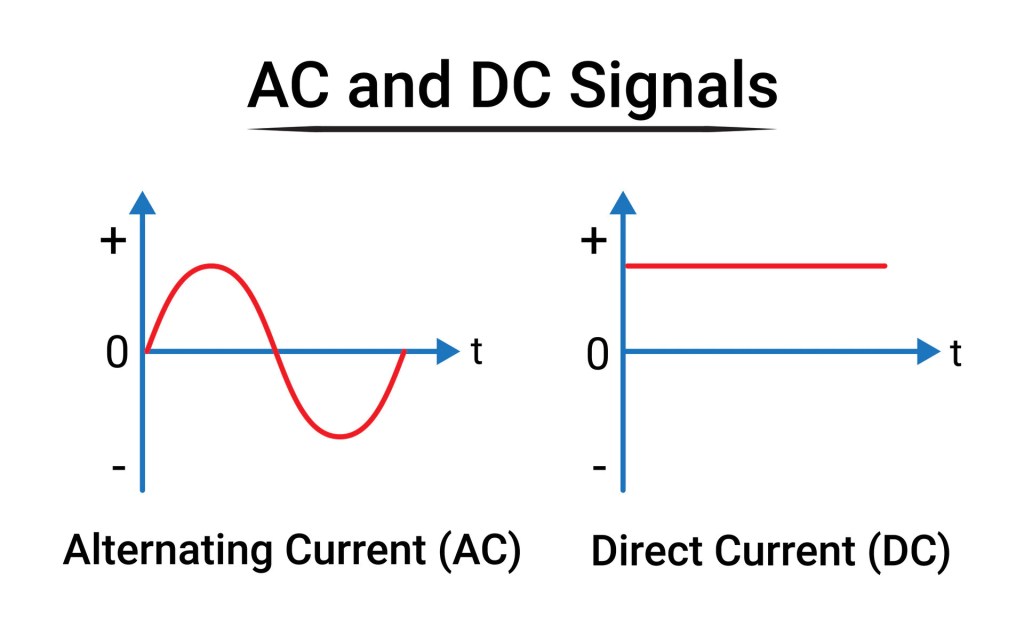
Direct current (DC) is an electric charge that flows consistently in a single direction, unlike alternating current which reverses periodically. In DC circuits, the voltage is constant, meaning the electrical potential difference does not vary with time. This type of current is commonly stored in and supplied by batteries, fuel cells, and solar panels. While DC is not typically used for long-distance power transmission due to greater energy loss and conversion limitations, it is essential for many low-voltage applications such as electronics, electric vehicles, and some types of medical and monitoring equipment. In the context of intraoperative neurophysiology and other biomedical applications, DC is usually avoided in stimulation protocols because it can cause tissue damage due to electrochemical buildup at the electrode-tissue interface.
Alternating current (AC) is an electric current that changes direction periodically – typically at a frequency of 60 Hz (cycles per second) in North America and 50 Hz in many other parts of the world. AC is the standard form of electricity used in homes, offices, and industrial settings. One of its major advantages over DC is that it can be easily transformed to different voltages using transformers, making it highly efficient for long-distance power transmission via the electrical grid. The sinusoidal nature of AC allows for easier generation and distribution, and it interacts with capacitive and inductive elements in circuits, leading to considerations like impedance and phase shifts. In medical applications, including neuromonitoring, the presence of ambient AC power (e.g., 60 Hz noise) is a common source of electrical interference and must often be filtered out from bioelectric signals.
Impedance (Z) is the total opposition that a circuit presents to the flow of alternating current. It is a complex quantity, measured in ohms (Ω), and encompasses both resistance (the opposition to current flow due to resistive elements like wires and resistors) and reactance (the frequency-dependent opposition caused by capacitors and inductors).
In other words, impedance takes into account not only how much a material resists current flow, but also how it stores and releases energy in the form of electric and magnetic fields. This concept is particularly important in AC circuits and in systems that handle signals with varying frequencies, such as EEG, EMG, and other neurophysiological recordings. In intraoperative neuromonitoring, impedance measurements are used to verify good electrode contact with tissue: Too high an impedance may indicate poor electrode placement, drying, or open circuits, while too low may suggest shorting or bridging between electrodes.
Electrode impedance should be kept below 2500 ohms to reduce noise and ensure high-fidelity signal recording. We measure this before and sometimes during surgery to maintain recording quality. Always check your impedance before beginning monitoring to ensure electrodes are secure and plugged in!
Inductance and Electromagnetic Interference
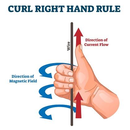
Two fundamental rules of electromagnetism matter here:
1) A current-carrying wire creates a magnetic field perpendicular to the current (Right-Hand Rule).
2) A changing magnetic field induces a new current in nearby conductors.
In the OR, this means that any electrical device – especially those running at 60 Hz – can generate electromagnetic noise. This includes cautery units, fluid warmers, and surgical microscopes.
To mitigate this:
1) Distance is your best friend. Move cables and electrodes away from power sources.
2) Orientation matters. Rotating a device may reduce the strength of its EM field hitting your leads. Lowering the device, if possible, can help as well.
3) Cable shielding and twisting lead wires can help reject common-mode interference. Don’t let your cables become frayed – Replace them if they do!
Electronics Matter in IONM
Understanding basic electronics empowers IONM professionals to optimize signal quality, troubleshoot noise, protect patients from electrical risks, and communicate effectively with surgical and anesthesia teams about interference sources. You may have complete mastery of neuroanatomy, but do not skip over the essentials of basic electrical components and electrical theory!
Effective communication and teamwork is essential for the delivery of high quality, safe patient care.
Failures to communicate are the leading cause of inadvertent patient harm.
Closed-loop communication (CLC) is essential for safety and precision in healthcare, particularly during complex surgeries involving intraoperative neuromonitoring (IONM). The neuromonitoring clinician cannot effectively do their primary function without clearly and confidently communicating baseline data, early changes, wave loss, or stimulation results.
(I would say in the context of an “early change”, anything that is an immediately noticeable trace-to-trace difference that I can’t attribute to a technical or anesthetic factor warrants at least a brief notification.)
In surgical environments, situational awareness is vital. CLC enhances this awareness by ensuring that all information is not only shared but acknowledged and confirmed by the appropriate team members.
Phrases like “Dr, I have a complete loss of right leg and foot MEP responses” or “Responses have returned after increasing the MAP” must be acknowledged aloud by the surgeon or anesthesiologist to confirm shared understanding and coordinated action.
Teams should use effective tools and structured communication behaviors, such as the SBAR technique (Situation, Background, Assessment, Recommendation). For example:
S: “We’ve lost MEPs in the left lower extremity.”
B: “Signals were stable prior to osteotomy.”
A: “This may indicate some level of spinal cord compromise.”
R: “Recommend surgical pause, increase in MAP, and re-testing after a few minutes.”
Using critical language – clear, standardized phrases that denote urgency or required action – also supports rapid response. Terms like “Signal loss,” or “Absent after…,” convey priority issues that must be addressed without delay. Hinting and hoping that you have been heard is fraught with hazard.
There is a hierarchy in medicine, and while it may be difficult to speak up with concerns due to certain power structure, cultural norms, or uncertainty, the ability to get everyone to stop and listen is essential for safe care. The reliability of IONM is threatened when the clinician’s role is neglected, and the decision to change course of a surgery relies heavily upon the communicator.
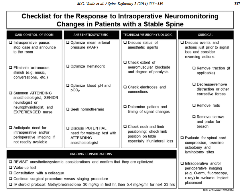
Checklists can be extremely useful to ease cognitive burden when faced with potential significant changes. And while there’s no substitute for being having situational awareness, we must all be cognizant and anticipate “the next steps” when dealing with waveform loss. See the following from Vitale 2014, a classic in the IONM world.
As neuromonitoring clinicians, we must overcome the heavy cognitive bias of the surgeon when there is a change. They will (understandably) want to see their carefully planned procedure through to the end, and experience with changes and patients waking with no or extremely minimal deficit can prohibit taking action when there is potentially serious change.
Maintaining team alignment through frequent communication about patient history, surgical milestones, and frequency of testing ensures the neuromonitoring clinician is integrated – not isolated – in the care process.
Ultimately, we must all be accountable for the patient. Every team members commitment to structured, reliable communication, shared awareness, and mutual respect ensures the best possible outcome for the patient.
For more reading, I suggest:
Dormans JP: Establishing a standard of care for neuromonitoring during spinal deformity surgery. Spine (Phila Pa 1976). 35:2180–2185, 2010
Leonard M, Graham S, Bonacum D: The human factor: the critical importance of effective teamwork and communication in providing safe care. Qual Saf Health Care; 13 (Suppl 1):i85-i90, 2004
Vitale MG, Skaggs DL, Pace GI, Wright ML, Matsumoto H, Anderson RC, et al: Best practices in intraoperative neuromonitoring in spine deformity surgery: development of an intraoperative checklist to optimize response. Spine Deform 2:333–339, 2014
What is intraoperative neuromonitoring (IONM), and why is it important?
Other than being an absolute mouthful of syllables, IONM is a means of assessing aspects of the central and peripheral nervous system during surgical procedures. These procedures range from orthopedic spine, cranial and spinal neurosurgery, urological, interventional radiology, vascular, and ear nose & throat (ENT) surgeries. The goal of IONM is to identify neural insults that would otherwise be undetected. Interventions can then be taken to eliminate or minimize potentially irreversible damage to the nervous system and prevent a potentially devastating postoperative deficit.
IONM is typically performed by a dedicated neurophysiologist or IONM clinician who works under the direct supervision of a professional (neurologist, neurophysiologist, audiologist). It forms a multidisciplinary team along with anesthesia and surgical personnel to deliver care.
An intraoperative neuromonitoring clinician should be trained to set up, troubleshoot, and operate IONM systems. They place electrodes, run various studies, and record intraoperative events and physiological parameters during the procedure.
Ultimately, IONM serves as a real-time safeguard for the nervous system, offering surgeons and anesthesiologists critical insight when it matters most. The ability to detect and respond to changes in neural function before permanent damage occurs has transformed the standard of care in high-risk procedures.
With ongoing advancements in technology and training, intraoperative neuromonitoring will remain an essential part of modern surgical practice, protecting what matters most: the patient’s quality of life.
This is an extremely broad overview, and in the coming weeks/months/years I hope to expand in great detail what it means to be a neuromonitoring clinician!
But being early permits you to take advantage of a lot.
First, the earlier you are, the more likely you are to learn that your case has canceled because your patient had coffee with cream and you can go back to bed. Kidding. Sort of.
Many of us performing IONM are not employed by a hospital system, but rather are contracted clinicians through a third-party company. Technically, we can show up basically whenever, as long as we get the job done. But…
The best advantages, in my mind, come from the reduced stress and anxiety of setting things up. Ask yourself: “Do I have all of the tools I need for today? Probes, check. Stimulator clips, check. Electrodes, check.”
Do I have ample time to turn on my system and confirm its proper functioning? There’s nothing worse than a patient rolling in the room and your MEP stimulator isn’t connecting and you need a new one. You could have figured that out before anesthesia started!
Being early allows you to shape your workspace and mentally prepare your flow. Early hours are often quieter, offering better concentration and fewer interruptions. Preparedness is confidence, and confidence is calming. Not just to you, but to everyone in the room.
I recently did monitoring for a case where I called before I left for an afternoon start, confirmed on-time, showed up, and the patient was being positioned. It happens. I was wholly unprepared, and although I knew what I was doing, the setup was extensive and I was definitely not calm. In fact – I could’ve been better. Luckily I had a patient surgeon and good data, but I did not know what I was walking into because I had nothing prepared and hadn’t spoken to the patient.
After that case, I remained on high stress for a little while after. I feel that when your workday begins slowly and smoothly, you are much less likely to carry that tension home, which enhances work-life balance.
In general, my rule of thumb is: Clothes changed into scrubs 1 hour before first-start cases, 1.5 hours before afternoon starts. Let me know when you like to show!